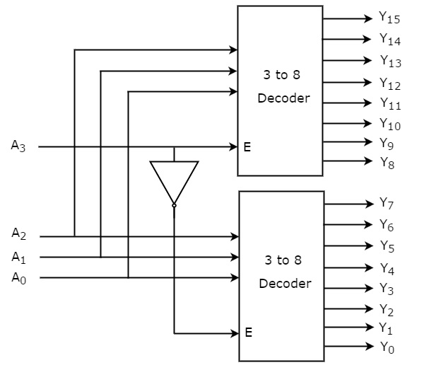
The following configuration shows 3 × 8 decoder with 2 × 4 decoders 2 × 4 Decoder EN B 1 Y 4 Y 5 Y 6 Y 7 B 0 2 × 4 Decoder EN B 1 B 2 Y 0 Y 1 Y 2 Y 3 B 0 When B 2 = 0, top decoder is enabled and other is disabled, for 000–011 inputs, outputs are Y 0 – Y 3, respectively, and other outputs are 0 For B 2 = 1, the enable conditions areA decoder is a combinational logic circuit that does the opposite job ofHence we can use 4 × 16 decoder for this But we were only given 2 × 4 decoders So 4 decoders are required in inner level as from one 2×4 decoder we have only 4 output lines whereas we need 16 output lines Now to point to these 4 decoders, another 2×4 decoder

Combinational Circuits Tutorialspoint
Active low 2 to 4 decoder truth table
Active low 2 to 4 decoder truth table-Jun 30, 15 · The truth table of an octal – to – binary priority encoder is shown below This type of encoder has 8 inputs and three outputs that generate corresponding binary code A priority is assigned to each input so that when two or more inputs are 1 at a time, the input with highest priority is represented in the outputNov 14, 16 · Construct a truth table using the relationship between the input and output;


Digital Circuits Decoders Tutorialspoint
For example, a 24 decoder might be drawn like this and its truth table (again, really four truth tables, one for each output) is 3 A 2 × 4 line decoder may acts like a 14 demux and viceversa 4 Decoder contains AND gates or NAND gates Decoder Applications 1Mar 10, 11 · Obtain the PLA program table with only seven product terms for a BCD to Excess 3 code converter Also give the fuse map ( Nov 08) Realize S(x,y,z) = S(1,2,4,5) using an appropriate decoder and an external logic gate Construct a 5 x 32 decoder with four 3 x 5 decoders and a 2×4 decoder use block diagrams ( Nov 08)Apr 12, · Download HS Computer Application Suggestion 21 PDF for Class 12 (WBCHSE) HS 21 Modern Computer Application Suggestion for test and final exam WBCHSE Suggestion 21 for West Bengal Higher Secondary Examination's well preparation HS Computer Application Suggestion 21 (Full Suggestion) – 98% Must Common Download PDF
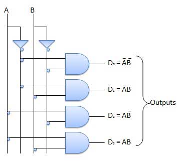
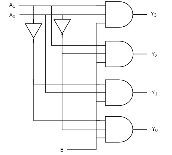
Hint it might be easier to eyeball a truth table than to do this by algebraic manipulation Implement using a multiplexer based on a 4 Show the logic gates needed to implement a 2×4 decoder, include an enable input Logic diagram for a 2×4 decoder, just use gatesMay 31, 21 · In swiprolog, the truth tables are predefined Code implementation Here, we will implement the logic and will write the code in prolog Step1 Here, we will implement the truth tables of all logic gates for 2 inputs A and B % Made by Maninder kaur % Following are the truth tables of all logic gates for 2 inputs A and B and(0,0,0)A decoder is a multipleinput, multipleoutput logic circuit that converts coded inputs into coded outputs, where the input and output codes are different Figure 17 shows a 2 × 4 decoder The behaviour of mentioned conventional circuit is defined as follows (3) F 1 = A ′ B ′, F 2 = A ′ B, F 3 = A B ′, F 4 = A B Figure 17 2 × 4
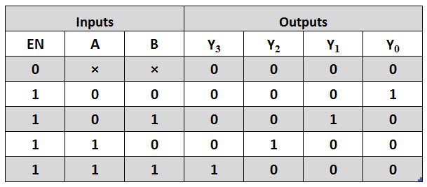
Nov 14, 16 · 2 × 4 Decoder Tutht table of 2 × 4 Decoder Encoders It is a combinational circuit that converts information into coded form (binary) It is a digital circuit that performs the inverse operation of a decoder An encoder has 2 n (or fewer) input lines and n output lines The output lines generate the binary code corresponding to the input valueA truth table written this way is sometimesThe truth table for 3 to 8 decoder is shown in table (1) From the truth table, it is seen that only one of eight outputs (DO to D7) is selected based g language Symbol The fig1 depicts 2 to 4 decoder schematic symbol and following is the truth table for the same ;


5 32 Decoder Design Using 4 3 8 Decoders And 1 2 4 Decoder In Verilog Code Stall


Reference Chapter 3 Moris Mano 4th Edition Ppt Download
Apr 17, 21 · 2 × 4 Decoder Tutht table of 2 × 4 Decoder Encoders It is a combinational circuit that converts information into coded form (binary) It is a digital circuit that performs the inverse operation of a decoder An encoder has 2 n (or fewer) input lines and n output lines The output lines generate the binary code corresponding to the input valueOct 01, 18 · The block diagram of 2 to 4 decoder is shown in the following figure One of these four outputs will be '1' for each combination of inputs when enable E is '1' The truth table of 2 to 4 decoder is shown below From truth table, we can write the Boolean functions (logical expressions) for each output asSep 01, 16 · Table 3 and Fig 3 (a), show the truth table and the schematic diagram of the proposed addressed 2×4 Decoder A total 4 clock zones or 1 clock cycle are required to synchronize the entire circuit In the proposed design the outputs of any Majority Voter (MV) acts as the input to the next MV at the same clock zone


Types Of Binary Decoders Applications


Experiment 1 Decoder Part15combination Logic Circuit Ares
(1 Mark) (e) Explain the functioning of a 2× 4 Decoder You should draw its truth table and explain its logic diagram with the help of an example input (2 Marks) (f) Assume that a source data value 1001 was received at a destination as 1101Viii) A decoder with 64 output lines has _____ data inputs a) 64 b) 1 c) 6 d) None of these ix) The number of flipflops required to build a Mod15 counter is a) 4 b) 5 c) 6 d) 7 x) The full form of CCD is a) Chargedcouple disk b) Chargecoupled device c) Cache coupled device d)The truth table of the function is shown below 0 2 × 1 1 Y A A MUX 0 1 Y A B C A B C Fig (4) 2 Demultiplexer A demultiplexer basically rev F e irg se (s4)the multiplexing function It is take data from one line and distribute them to given number of output lines Fig (3) shown a one to four line demultiplexer circuit


Binary Decoder Construction Types Applications


Combinational Circuits Tutorialspoint
Feb 26, 14 · Decoder is significant component and it is utilized in many logical and functional circuits A decoder is a multipleinput, multipleoutput logic circuit that converts coded inputs into coded outputs, where the input and output codes are different Figure 17 shows a 2 × 4 decoder The behaviour of mentioned conventional circuit is defined as2×4 Decoder The Boolean function is listed in a truth table 2 The first −1 variables in the table are applied to the selection inputs of the MUX 3 For each combination of the selection variables, evaluate the output as a function of the last variable 4 The values are then applied toA is false but R is true A demultiplexer can be used as a decoder Explanation Decoder Generally, a decoder converts a binary number into any other format (decimal, hexadecimal, etc) Eg 2 × 4 decoder Truth table


Digital Circuits Decoders Tutorialspoint


Binary Decoder What Is It Truth Table And Logic Diagram Electrical4u
Nov 02, 16 · It should be noted that the used transistors in the gated OPV molecular circuit model (molecular transistor) are level 1 with parameters KP = 5E7, γ = 0586, λ = 0, V = To Fig 2 Schematic model of a 2 × 4 decoder (above) and its truth Table V (V = 01 V for MYNMOS2 and V = 02Vfor th To To (below) MYNMOS4) 17Download Digital Technologypdf Abdualrahman Kdh 11 EXPERMENT NUMBER (1) LOGIC GATES AND BOOLEAN ALGEBRAAfter completing this experiment, you will be able to OBJECT1Use TTL logic to verify experimentally several of rules for Boolean algebra2Experimentally determine the truth table for circuits with two input variables THEORYIn analog2 to 4 Line Decoder Truth Table In this type of decoders, decoders have two inputs namely A0, A1, and four outputs denoted by D0, D1, D2, and D3 As you can see in the following truth table – for every input combination, one o/p line is turned on


How Can I Construct 2 4 Decoder Circuit With The Help Of Ic 74xx139 Electronics Forums


4 16 Decoder Design Using 2 4 Decoder Youtube


0 件のコメント:
コメントを投稿